Heat Sinks – Ultra Cool Series
Overview UltraCool III
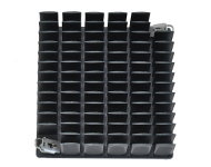
Forged out of pure aluminum, UltraCool III pin fin heat sinks provide outstanding cooling solutions for SM devices.
· UltraCool III heat sinks are designed for situations in which substantial cooling power is required and for applications in which the space available for cooling is limited.
· The UltraCool III line offers a wide array of solutions for any package type and size.
· UltraCool III heat sinks can be customized to any required footprint or height in a cost effective fashion.
All electronic components generate heat during their operation. This heat increases the temperature of the components and if not dissipated at a proper rate will burn the component or reduce substantially the component’s service life.
To remove the generated heat, air is generally used. The heat dissipation rate depends on air velocity, surface area in contact with the flowing air and temperature difference between air and the hot surface in contact with the air. In many cases the surface area of the component in contact with the air is too small to remove the generated heat at the permitted temperature difference between the component surface and the air. To increase the surface area in contact with the flowing air a heat sink is used. The heat sink is usually made from aluminum or copper and is composed of a flat base which is thermally attached to the top of the component absorbing the heat generated by the component. From the base protrude large number of pins or continuous fins comp[rising large surface area in contact with the air. The fins or pins absorbs the heat from the base and transfer the heat to the cooling air flowing among the fins.
In most cases the air flow is generated by a fan or fans which are either remotely disposed in respect to the heat sink, such as on the wall of the enclosure while in other cases such as with CPU COOLERS the fan is mounted on the heat sink above the fins blowing the cooling air directly on the fins and base.
The heat sink is characterized by its thermal resistance which is defined as the amount of heat the heat sink can dissipate at a given temperature difference between the average temperature of the base and the temperature air flowing into the heat sink. The thermal resistance decreases exponentially as a function of air velocity, between zero air velocity = natural convection to 3 m /sec, after which the thermal resistance remains unchanged.
Heat sinks are referred to also as heat dissipaters,
Small heat sinks are manufactured by stamping, forging, casting or machining. Large heat sinks are manufactured by extrusion or by swaging, adhering , brazing or soldering the fins to the base.
Key Features
· Outstanding cooling power
· Low pressure drop
· Easily tailored to any footprint or height
· A wide selection
· Powerful low airspeed solutions
· Unique miniature solutions
Overview UltraCool IV
· Forged out of oxygen-free copper, UltraCool IV heat sinks provide exceptional cooling power.
· UltraCool IV heat sinks are suitable for devices that generate heavy heat loads, for devices that contain small and focused heat sources and for space-constrained applications.
· Due to the highly conductive nature of oxygen-free copper, UltraCool IV heat sinks offer the functionalities of both a heat sink and a heat spreader.
Key Features
· Exceptional cooling power
· Outstanding heat spreading abilities
· Function as a heat sink and a heat spreader
· Suitable for extremely hot devices
· Suitable for small and focused heat sources
· Ideal for open flip-chip devices
All electronic components generate heat during their operation. The generated heat increases the temperature of the components and if not removed at a proper rate will burn the component or reduce substantially the component’s service life.
To remove the generated heat from hot components, flowing air is generally used. If the surface of the component is too small to dissipate the heat to the air a heat sink made from aluminum or copper is used. Theheat sink is composed of a flat base which is thermally attached to the hot top surface of the component, absorbing the heat generated by the component. From the base protrude a large number of pins or continuous fins among which the cooling air is flowing. The fins or pins absorbs the heat from the base and due to their large contact surface area with the air transfer the heat to the cooling air in contact with the fins.
Because the surfaces of the heat sink base and the component’s top comprises tiny irregularities and bumps, said surfaces form contact with each other at random on about 5% to 10% of the whole surface area. The rest 90% of the area comprised tiny gapes filled with trapped air of very low thermal conductivity leading to very low overall thermal conductivity between said two surfaces. To remove the air, thermally conducting materials in the form of : pads, tapes, pastes, gels, phase change materials (PCM) and elastomers, and generally – thermal interface material (TIM). The TIM are placed between the two surfaces, and with pressure being applied penetrate into said gapes and irregularities, removing the trapped air and replacing the air with a material of much higher thermal conductivity than that of the air while substantially improving the heat flow from the component to the heat sink base. The TIM main characteristics to considered are – highest thermal conductivity, good conformability so as to enable to form thermal contact with maximal surface area of said bumps and irregularities, minimal thickness to reduce the heat-flow path and the thermal resistance.
All electronic components generate heat during their operation. This heat increases the temperature of the components and if not dissipated at a proper rate will burn the component or reduce substantially the component’s service life. Some component such as laser diodes must dissipate the heat while remaining at constant temperature to enable to generate a specific wave length. This task is accomplished by using thermoelectric modules or thermoelectric coolers which are generally referred to as TEM.
TEM are elements composed of special semi conducting crystals which utilizes the Peltier phenomena to cool electronic component and other items such as wine bottles. When said crystals are subjected to a suitable direct voltage a current is pumped into the crystals which cools down one end of the crystal and warms up the other end. When the voltage is reversed the cold side warms up while the hot side cools down. The crystals can be produced as P or N type which act oppositely is respect to the current flow. With P and N crystals are properly soldered to a circuit printed on a none electrically conducting and thermally conducting substrate such as ceramic plate, a TEM is formed. When current is pumped through the TEM, one plate turns cold and the other hot. Reversing the current will reverse the cold plat into hot one and the hot into cold one.
With the module’s cold side attached to a hot surface of a heat generating component the cold plate absorbs the heat from the component, transferring it to the hot plate. The heat is removed from the hot plate to the ambient generally by air operated heat sink or water cooled cold plate.
The TEM is capable to keep a component at fixed temperature regardless the ambient temperature with an accuracy of one tenth of a degree.
The amount of heat transferred by the TEM from the component to the ambient multiplied by the temperature difference between the cold and hot plates is defining the capacity of the TEM, this energy is supplied to the TEM by the current pumped into the TEM. The hot side has to dissipate also the pumped energy otherwise it will burn out.